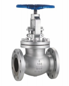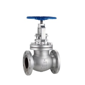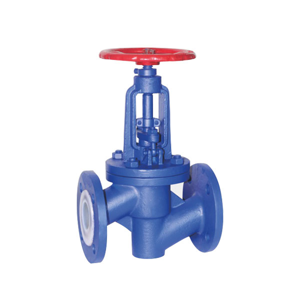
Features of flange type fluorine lined globe valve
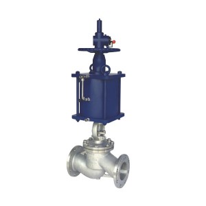
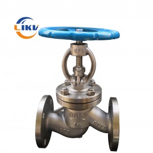
1. J41f series fluorine lined globe valve refers to the valve whose closing part (disc) is driven by the stem and moves up and down along the center axis of the valve seat. It is mainly used to connect or cut off the medium in the pipe, but it can not be used for throttling. It has the characteristics of compact structure, flexible opening and closing, strong corrosion resistance and short stroke.
2. The disc and stem are designed as an integrated structure to prevent the possibility of the internals from rushing out of the valve body due to the fluctuation of pipeline pressure. The structure is compact and safe.
Executive standard for flange type fluorine lined globe valve
| Product specification | design code | Structural length | Connecting flange | Test and inspection |
| HG/T3704、GB12235 | GB/T12221 | JB/T 79、GB/T9113、HG/T20592EN1092-1/2、ASME B16.5/B16.47 | JB/T 9092GB/T13927、API598 |
Material of main parts
| Serial number | Part name | Investment cast ductile iron | carbon steel | stainless steel | |||
| QT | C | P | R | PL | RL | ||
| 1 | Body / bonnet / disc | QT400 | WCB | CF8 | CF8M | CF3 | CF3M |
| 2 | Stem | 20Cr13 | 20Cr13 | 1Cr18Ni9 | 1Cr18Ni12Mo2Ti | 00Cr18Ni10 | 1Cr17Ni14Mo2 |
| 3 | Live bolt | 35 | 35 | 1Cr17Ni2 | 1Cr17Ni2 | 1Cr17Ni2 | 1Cr17Ni2 |
| 4 | Lining layer | PTFE (F4) 、FEP (F46) 、PFA、PO | |||||
| 5 | filler | PTFE (F4) | |||||
| 6 | Packing gland | WCB | WCB | CF8 | CF8M | CF3 | CF3M |
| 7 | Bolt | 35 | 35 | 1Cr17Ni2 | 1Cr17Ni2 | 1Cr18Ni9 | 1Cr18Ni9 |
| 8 | Nut | 45 | 45 | 0Cr18Ni9 | 0Cr18Ni9 | 0Cr18Ni9 | 0Cr18Ni9 |
| 9 | handwheel | A3 | |||||
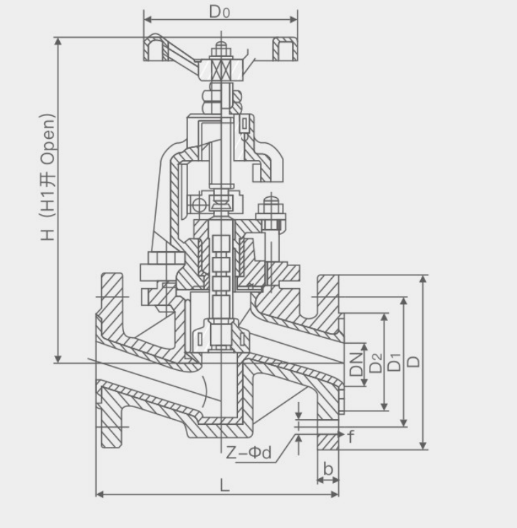
Drawing of flange type fluorine lined globe valve
Main performance specification for flange type fluorine lined globe valve
| model | Nominal pressure | Test pressure | working temperature | Applicable medium | |
| housing | seal up | ||||
| J41F4-16 | 1.6 | 2.4 | 1.76 | ≤180 | Sulfuric acid, hydrofluoric acid, phosphoric acid, chlorine, strong alkali, aqua regia and other corrosive media |
| J41F46-16 | ≤160 | ||||
Main connection dimensions J41F4/F46-16
| Nominal diameter(DN) | L | D | D1 | D2 | b | f | H | H1 | D0 | Z-Φd |
| 15 | 130 | 95 | 65 | 45 | 16 | 2 | 240 | 265 | 100 | 4-Φ14 |
| 20 | 150 | 105 | 75 | 58 | 18 | 2 | 240 | 265 | 100 | 4-Φ14 |
| 25 | 160 | 115 | 85 | 68 | 18 | 2 | 240 | 265 | 120 | 4-Φ14 |
| 32 | 180 | 140 | 100 | 78 | 18 | 2 | 260 | 290 | 140 | 4-Φ18 |
| 40 | 200 | 150 | 110 | 88 | 18 | 2 | 290 | 325 | 140 | 4-Φ18 |
| 50 | 230 | 165 | 125 | 102 | 18 | 2 | 300 | 335 | 160 | 4-Φ18 |
| 65 | 290 | 185 | 145 | 122 | 18 | 2 | 355 | 400 | 180 | 8-Φ18 |
| 80 | 310 | 200 | 160 | 138 | 20 | 2 | 400 | 450 | 240 | 8-Φ18 |
| 100 | 350 | 220 | 180 | 158 | 200 | 2 | 495 | 455 | 240 | 8-Φ18 |
| 125 | 400 | 250 | 210 | 188 | 22 | 2 | 530 | 560 | 280 | 8-Φ18 |
| 150 | 480 | 285 | 240 | 212 | 22 | 2 | 650 | 605 | 320 | 8-Φ22 |
| 200 | 600 | 340 | 295 | 268 | 24 | 2 | 650 | 770 | 360 | 12-Φ22 |
| 250 | 730 | 405 | 355 | 320 | 26 | 2 | 690 | 810 | 400 | 12-Φ26 |